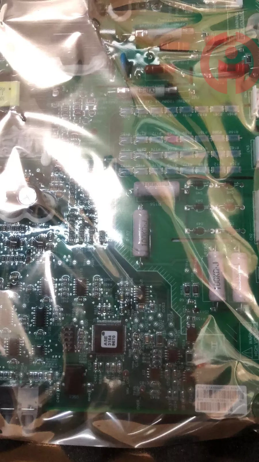
Siemens Robicon Control board
Origin: Germany
Brand: Siemens
The Siemens A1A10000432.30M control board is a key component in Siemens high-voltage frequency converters, mainly used to receive signals from the main control system, provide control signals to the drive board, perform real-time fault monitoring, report fault information to the main control system, and finally supply power to the control board itself.
Product Introduction
Receiving signals from the main control system: The control board receives signals from the main control system and transmits them to the drive board to control the operation of the frequency converter.
Real time fault monitoring: The control board has real-time fault monitoring function, which can timely report fault information to the main control system when a fault occurs, ensuring the safe operation of the system.
Power supply: The control board itself also needs power supply, usually through a 24V DC power supply.
Interface and connection method
Fiber optic interface: used for communication with the main control system.
24V power input interface: Connect to the power board to obtain 24V DC power.
Driver signal interface: including Top1, Top2, and/Lock interfaces, used to connect with the driver board.
15V power output interface: supplies power to the driver board.
Overvoltage and undervoltage detection interface: connected to the positive and negative busbars of the unit to detect voltage status.
Phase loss detection interface: connected to fuse auxiliary switch.
Overheating detection interface: connected to temperature detection switch.
Power on thyristor drive signal interface: Connect to the thyristor gate.
Bypass thyristor drive signal interface: connected to the bypass thyristor gate.
Bypass OK signal detection interface: connected to the bypass OK board.
Through these interfaces and connection methods, the control board can effectively communicate and exchange data with other parts of the system, ensuring the normal operation and fault monitoring of the high-voltage inverter.
Many products have not been listed yet. Please contact us for more products If there is any
inconsistency between the product modeland the displayedpicture,the model shall prevail.
Please contact us for specific product pictures, and we will arrange for photos to be taken in the warehouse for confirmation
Technical Team Service Hotline:0591-85299001