
SIEMENS Frequency Converter 6SE7041-4WM84-1CF0
SIEMENS Frequency Converter
Origin: German
Brand: SIEMENS
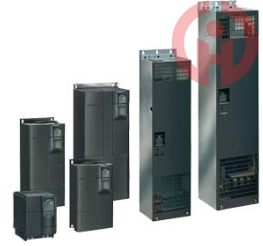
Siemens inverter 6SE7041-4WM84-1CF0 is a high-performance drive solution, especially suitable for motions that require frequent changes in speed or direction of rotation, and occasions that require electric braking. This inverter is not only suitable for driving conveying vehicles and stage machinery equipment in theaters, but also for driving loads with high inertia moments such as heavy-duty transportation systems and conveyors.
SIEMENS Frequency Converter
Origin: German
Brand: SIEMENS
Siemens inverter 6SE7041-4WM84-1CF0 is a high-performance drive solution, especially suitable for motions that require frequent changes in speed or direction of rotation, and occasions that require electric braking. This inverter is not only suitable for driving conveying vehicles and stage machinery equipment in theaters, but also for driving loads with high inertia moments such as heavy-duty transportation systems and conveyors.
Product Introduction
6SE7041-4WM84-1CF0For 8-bit modules, input and output each occupy one byte, and they have the same byte address. If fixed slot addressing is used, SM323 is inserted into slot 4, then the input address is I4.0 to I4.7, and the output address is Q4.0 to Q4.7. Check whether the ungrounded sensor installed on the insulating rack is being used or check whether your sensor is grounded. When using CP340, CP341 to communicate with the PC, data is often not read. There are two reasons for this. . Function blocks for SimaticS7-300/-400/-1200/-1500 are provided in the Step7 software.
Working principle of German Siemens DC speed regulator
Working principle of DC speed regulator
DC speed regulator is a device for regulating the speed of DC motor. The upper end is connected to the AC power supply and the lower end is connected to the DC motor. The DC speed regulator converts AC power into two output DC power supplies, one for DC motor magnetization (stator) and one for DC motor armature (rotor). The DC speed regulator adjusts the speed of DC motor by controlling the armature DC voltage. At the same time, the DC motor gives the speed regulator a feedback current. The speed regulator judges the speed of DC motor according to the feedback current and corrects the armature voltage output when necessary to adjust the speed of the motor again.
There are generally three ways to regulate the speed
1. Change the armature voltage; (the most commonly used scheme)
2. Change the excitation winding voltage;
3. Change the armature circuit resistance.
There are three types of DC speed regulation: rotor series resistance speed regulation, voltage regulation speed regulation, and weak magnetic speed regulation.
Rotor series resistance is generally used in low-precision speed regulation occasions. After the resistance is connected in series, the mechanical characteristic curve becomes soft, so it is generally used in reverse pull and reversing loads.
Voltage regulation speed regulation, the mechanical characteristic curve is very hard, and the speed can be adjusted while ensuring that the output torque remains unchanged, so it is easy to achieve high-precision speed regulation.
Weak magnetic speed regulation, because the motor speed increases after weak magnetic field, it is generally used in conjunction with voltage regulation speed regulation. Disadvantages: small speed regulation range and can only increase speed but not decrease speed. Improper control is prone to runaway problems.
DC speed regulator is a motor speed regulation device, including motor DC speed regulator, pulse width DC speed regulator, thyristor DC speed regulator, etc. It is generally a modular DC motor speed regulator, which integrates power supply, control, and drive circuits. It adopts a three-dimensional structure layout, and the control circuit adopts micro-power consumption components. Optocouplers are used to achieve current and voltage isolation conversion. The proportional constant, integral constant, and differential constant of the circuit are adjusted with a PID adapter. The speed regulator is small in size and light in weight. It can be used alone or directly installed on a DC motor to form an integrated DC speed regulation motor, which can have all the functions that a speed regulator should have.
6SE7041-4WM84-1CF0 If an error in the power supply (S7-400 only) or in the buffer triggers an event, the CPU operating system accesses OB81. After the error is corrected, access OB81 again. In the case of battery failure, the S7-400 only accesses OB81 if the BATT.INDIC switch in the battery test is activated. If OB81 is not configured, the CPU does not enter the operating state STOP. If OB81 is not available, the CPU remains running when the power supply fails. DO address: 256-259 This gives the size of the memory required to save the entire project on an MMC. 59: What should I pay attention to when using the * encoder with FM357-2? The firmware version of FM357-2 is V3.2/V3.3. In the following cases, the sampling value of the * encoder may be incorrect. These problems will be solved when the FM357-2 firmware version is V3.4.
6RA8085-6DS22 debugging method:
1. Input P50100
2. Input 50101
3. P50102
4. P50750=63
5. P50755=68
6. P50770=1
7. P50771=2093.3
After optimization, alarm F60166 and F60167 are triggered, the fault is shielded, P2118.0=60167, then P2119.0=60167, alarm F60031 is triggered when the machine is stopped after optimization, and the deceleration time P50304 is changed from 10S to 20S.
IV. Motor start
After the above parameters are set correctly, the motor can be started with constant magnetism, P81=0, and the excitation current is connected
Source and motor fan, when P51=40, the transmission cabinet selects the switch input closing and unlocking commands, and the given speed is input by P402, and the motor rotates.
V. Check read-only parameters
R010: switch input, 0-6 bits correspond to the 36-42 terminal status, 12 bits correspond to the ESTOP signal
R011: switch output status, the 0th bit represents the 46 terminal serious fault, and the 7th bit represents 109/110
terminal and gate signal
R015: actual armature incoming line voltage 630V, should be within the allowable value range
R016: actual excitation incoming line voltage, should be within the allowable value range
R017: actual incoming line frequency, should be within the allowable value range
R038: actual armature DC voltage, the value should be close to 0 when the device is not unlocked.
R039: EMF given value, equal to P101-P100*P110
VI. Check the fan
Check the device fan
Check the motor fan
6SE7041-4WM84-1CF0 grounding sensor: Make sure the sensor has a good equipotential connection. Then isolate the connection from M to Mana and to the central grounding point. Please place the shielding layer on both sides. One-way connection: A CPU can send GD data packets to multiple CPUs. ②, control output and conversion module: Corresponding to the output conversion part in the figure, it is responsible for the range conversion of PID control output. Specific software includes Step7, Step7MicroWin, SimaticNet, WinCC, Protool, Flexible, PCS7.
6SE7041-4WM84-1CF0 parameters
Introduction to Siemens DC controller 6RA70
At present, with the development of AC speed regulation technology, AC transmission has developed rapidly, but DC transmission speed regulation still has a large number of applications in many occasions. With the development of computer technology, the past analog control system is being replaced by digital control system. In the universal all-digital DC speed control device with microcomputer, various adjustment and control functions can be easily realized by relying on software support without changing the hardware or with little modification. Therefore, the reliability and application flexibility of the universal all-digital DC speed control device are obviously better than the analog control system. At present, the 6RA70 series universal all-digital DC speed control device of SIEMENS Company of Germany is the most widely used in the world.
4. Actual speed detection parameter setting
P083 (F) = actual speed feedback selection
When P083 = 2 (pulse encoder), the maximum speed is the value of P143 parameter
When P083 = 3 (armature feedback), the maximum speed is the speed corresponding to the value of P115 parameter
P140 = 0 or 1, pulse encoder type selection. When armature feedback P083=3, set it to zero;
When encoder feedback P083=2, set it to "1".
P141=1024, pulse encoder pulse number per revolution
P142=1, encoder 15V power supply
P143(F)=* running speed (rpm) when encoder feedback
P148(F)=1, enable encoder monitoring (F048 fault is valid)
5. Excitation function parameter setting
P081=0 Constant magnetic operation mode (setting value before weak magnetic optimization)
P081=1 Weak magnetic operation mode (set when performing weak magnetic optimization, set to 1 after optimization)
P082=2 Excitation operation mode, after reaching the operating state>07, after the delay of P258, input
Economic excitation current P257.
P257(F)= 0 (%P102) Shutdown excitation
6SE7041-4WM84-1CF0⑤, background data block of PID controller. Used to store the control parameters of the PID controller and the historical data that needs to be saved in the control algorithm. Important: After resetting the PG/PC, communication with the CPU can only be established via the MPI or MPI/DP interface. Table 2-10 Cyclic program processing The cycle time of each user program cycle is not the same and may be extended by the following conditions: Different program paths Time-controlled interrupt processing Process interrupt processing (see the "Interrupt response time" chapter) Diagnostics and fault handling Communication between the connected CP (such as Ethernet, PROFIBUS-DP) and the programming device (PG) and operator panel (OP) Testing and debugging programs, such as the status and control of variables or block status functions Transfer and delete blocks, compress user program memory Use SFC82-84 in the user program to write/read access to the MMC Therefore, when monitoring the cycle time with STEP7, there will be two values: * Cycle time and * Minimum cycle time. The slot number label is included in the CPU.
I think you'll find our product offers great value for money!
It's my pleasure to introduce our latest product, which will be a great addition to your current offerings!
We're thrilled to introduce you to our latest product, which we believe will meet your needs perfectly!
We believe this product can help to expand your market share. We look forward to the opportunity to work with you!
We sincerely welcome your calls and consultations and provide you with quality service 24 hours a day!
· Many products are not yet on the shelves please contact us for more products.
· If there is inconsistency between the product model and the display picture, the model shall prevail, please contact us for specific product pictures, we will arrange to take pictures in the warehouse to confirm!
.Technical Team Service Hotline:wujinghan102@gmail.com +86 13376990653
Postal Code: 350300
Mobile: (+86) 15606940871
Email: zhddqjt@gmail.comAddress: Building 9, Liandong U Valley Economic and Technological Innovation Center, Yangxia Industrial Zone, Fuqing City, Fujian Province,China

Follow official account