
In the world of PLC, we mainly handle three types of data: switch quantity, analog quantity, and
pulse quantity. When you have a deep understanding of the relationship between these three
you can easily master the operation of PLC.
PLC Programming Algorithm (1)
1. Switching quantity, also known as logic quantity, has only two states: 0 or 1 and ON or OFF.
These two states reflect different working conditions, including input and output states.
Switching control is the core application of PLC. Through it, we can generate corresponding
outputs based on the current input combination and historical input sequence, thereby achieving
orderly operation of the system. This control method is sometimes referred to as sequential
control, which can be manually, semi automatically, or automatically adjusted according to
demand.
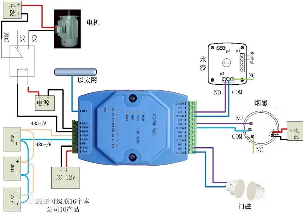
2. Analog quantities refer to physical quantities that continuously change, such as voltage, current, pressure, velocity, and flow rate. Although PLC was originally mainly used for switch control, it can reliably process analog signals because analog signals can be converted to digital signals. In continuous production processes, analog control is often referred to as process control. To achieve the conversion between analog and digital quantities, we need to use sensors to convert analog quantities into electrical quantities. If the electrical quantity is not standard, it also needs to be converted into standard electrical signals through transmitters, such as 4-20mA, 1-5V, 0-10V, etc. Next, these standard electrical signals are converted into digital signals through an analog input unit (A/D), and then processed by a PLC. Understanding the resolution of analog units and the standard electrical signals is key to performing this conversion.
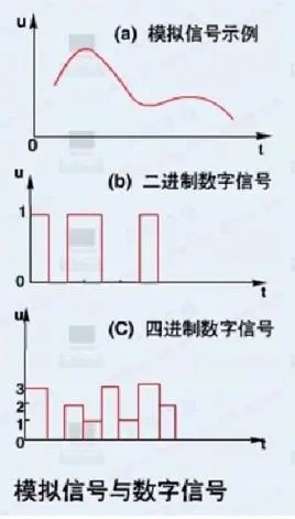
3. Pulse quantity is a special digital quantity whose value alternates between 0 (low level) and 1 (high level). The number of times pulses alternate per second is called frequency. In PLC, pulse control is mainly used for position control, motion control, and trajectory control. For example, in angle control, we can control the rotation angle of the stepper motor by calculating the required number of pulses. If the subdivision of the stepper motor driver is 10000 per revolution and the motor needs to rotate 90 degrees, then the required number of pulses is 10000 divided by (360/90), which is 2500 pulses.
PLC Programming Algorithm (2) - Calculation of Analog Quantity
1. When the voltage range is -10V to 10V, different resolutions will result in different hexadecimal
conversions. At a resolution of 6000, this voltage range is converted to hexadecimal values F448
to 0BB8, corresponding to a numerical range of -3000 to 3000. At a resolution of 12000, the
voltage range is converted to E890 to 1770Hex, corresponding to a digital range of -6000 to
6000.
2. For voltages ranging from 0V to 10V, the hexadecimal conversion range at 12000 resolution
is 0 to 1770Hex, corresponding to a numerical range of 0 to 6000. At a resolution of 12000, the
hexadecimal range is extended to 0 to 2EE0Hex, corresponding to a numerical range of 0 to 12000.
3. When the current ranges from 0mA to 20mA, the hexadecimal conversion range at 6000
resolution is 0 to 1770Hex, corresponding to a numerical range of 0 to 6000. At a resolution
of 12000, this range extends to 0 to 2EE0Hex, corresponding to a numerical range of 0 to 12000.
4. When the current is between 4mA and 20mA, its hexadecimal conversion is the same as when
it is between 0mA and 20mA. At a resolution of 6000, it ranges from 0 to 1770Hex, corresponding
to the numerical range of 0 to 6000; At a resolution of 12000, it ranges from 0 to 2EE0Hex
corresponding to the numerical range of 0 to 12000.
Please note that the above is only a brief introduction. Different PLCs have different resolutions
and the range of physical quantities measured may also vary, so the calculation results may differ.
Regarding the wiring requirements for analog inputs:
1. It is recommended to use shielded twisted pair cables for connection, but please ensure
that the shielding layer is not connected.
2. When an input is not in use, it is recommended to short-circuit the VIN and COM terminals
to avoid unnecessary interference.
3. Analog signal lines should be isolated from power lines (such as AC power lines, high-voltage
lines, etc.) to reduce electromagnetic interference.
4. If there is interference on the power line, it is recommended to install a filter between the
input section and the power unit to improve signal quality.
5. When wiring, please ensure that the connection is correct. First, power on the CPU unit, and
then power on the load to ensure the stable operation of the system.
6. When there is a power outage, it is recommended to first cut off the power supply to the load,
and then cut off the power supply to the CPU to avoid possible equipment damage or data loss.
PLC Programming Algorithm (3) - Calculation of Pulse Quantity
The control of pulse quantity is the key to achieving precise angle control, distance control, and
position control for stepper motors and servo motors. The following is an example of using a
stepper motor to illustrate various control methods:
Angle control of stepper motor:
The angle control of a stepper motor mainly depends on the number of details and the total
number of pulses required for one revolution. The subdivision number determines the minimum
angle of rotation for each step of the stepper motor, and the total number of pulses required for
one revolution is related to the model and subdivision number of the stepper motor.
By setting the target angle and calculating the angle percentage, we can determine the number
of pulses that need to be sent. The specific calculation formula is:
Number of angle action pulses=total number of pulses per revolution x (set angle/360 °)
This formula converts the target angle into the number of pulses that need to be sent, thereby
achieving precise angle control.
Distance control of stepper motor:
The distance control of stepper motors requires first determining the roller diameter and
calculating the roller circumference. For every revolution of the roller, the stepper motor needs
to complete a certain number of pulses. Therefore, we can calculate the number of pulses
required to set the distance by the circumference of the roller and the distance rotated per pulse.
The specific calculation formula is:
Set distance pulse count=Set distance/[(roller diameter × 3.14)/Total number of pulses per
revolution]
This formula converts the target distance into the number of pulses that need to be sent,
thereby achieving precise distance control.
Position control of stepper motor:
The position control of stepper motors is actually a combination of angle control and distance
control. By controlling the angle and distance of rotation of the stepper motor, we can achieve
precise control over its position. In practical applications, it may be necessary to combine
multiple sensors and feedback mechanisms to ensure that the stepper motor can accurately
reach the designated position.
For servo motors, their operating principle is similar to that of stepper motors, but the internal
electronic gear ratio and reduction ratio of the servo motor need to be considered. The
electronic gear ratio determines the proportional relationship between the number of pulses
received by the servo motor and the actual rotation angle, while the reduction ratio determines
the speed ratio between the output shaft of the servo motor and the internal rotor of the motor.
When controlling servo motors, corresponding adjustments need to be made based on these
parameters.
Postal Code: 350300
Mobile: (+86) 15606940871
Email: zhddqjt@gmail.comAddress: Building 9, Liandong U Valley Economic and Technological Innovation Center, Yangxia Industrial Zone, Fuqing City, Fujian Province,China

Follow official account